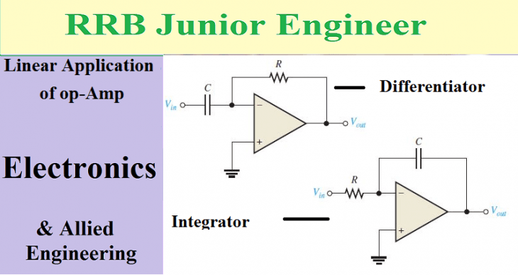
Integrator simulates mathematical integration of a function and differentiator simulates mathematical operation differentiation of a function. Here we are discussing about Integrator and Differentiator using opamp. Integration is basically a summing process that determines the total area under the curve of a function. Differentiation is determining
the instantaneous rate of change of a function.
Contents
Op-Amp Integrator
Ideal Integrator
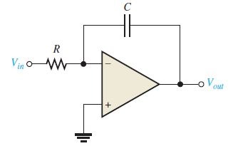
Input signal is connected to inverting terminal and non inverting terminal is grounded. Negative feedback technique is used where in feedback path a capacitor is used. In practical integrator this capacitor in the feedback path have a parallel resistor.
How a capacitor charges ?
To know the working of integrator, recall charging of a capacitor, When capacitor in RC circuit is charging, charging current decreases continuously thus capacitor voltage also decreases continuously (exponentially). In Opamp integrator charging current is made constant, thus a rate of change of voltage decreases as a straight line instead of exponential curve.
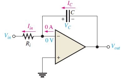
Consider above figure, Since the non inverting terminal of opamp is grounded. So inverting terminal is in virtual ground. Thus constant voltage supply generate only constant input current. Because of the high input impedance of opamp only negligible amount of current passes through the inverting terminal. In other words, input current completely passes through the capacitor in the feedback path.
Capacitor Voltage
Since the input current is constant and it is completely flowing through the capacitor.voltage across the capacitor decreases linearly.
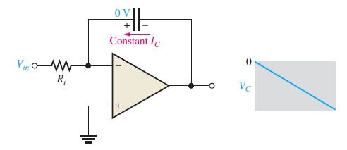
across the capacitor by the constant
charging current
Positive side of the capacitor remains zero volt, Because of the virtual ground. Negative side’s voltage linearly decreases from zero and form a negative ramp.
Output Voltage
Output voltage is same as that on the negative side of the capacitor. When a constant positive input voltage in the form of a pulse is applied, the output will be a ramp decreases negatively until opamps maximum negative saturation.
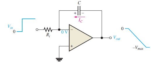
ramp on the output of the integrator
Rate of Change of the Output Voltage
Rate of Change of the Output Voltage is equal to the rate of change of the capacitor voltage. It is equal to

Integrator can be used to generate triangular wave oscillator.
Practical Integrator
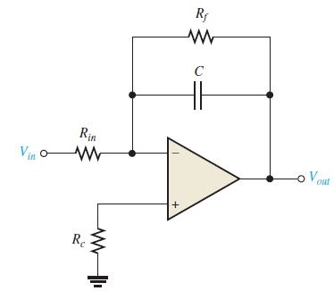
An ideal opamp integrator have only capacitor in the feedback path. But capacitor conducts only AC but not DC. When DC current passes is connected across the capacitor capacitor act as an open loop. This offest error can be avoided by connecting a feedback resistor parallel to this capacitor. This resistor should be larger than input resistance. And to balance this bias another resistor is connected to the non inverting terminal.
Op-Amp Differentiator
Ideal Differentiator
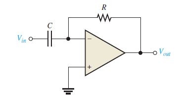
op-amp differentiator circuit have slight differences from opamp integrator. That is feedback capacitor is replaced by a resistor and input resistor is replaced by a capacitor. Differentiator produces an output which is proportional to the rate of change of the input voltage.
Working of opamp differentiator
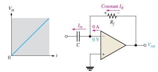
When a positive going ramp function is applied across the opamp differentiator. Voltage across the capacitor in the inverting terminal is also same as the ramp function. Because of the presence of virtual ground. Due to the high input impedance of opamp only negligible current is feed into the opamp, so input current completely flows through the current.
Since current across capacitor is constant (because of constantly increasing capacitor voltage ), current across resistor and output is constant. Since current in out put is constant, output voltage is constant (by ohms law).
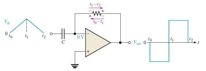
series of positive and negative ramps
(triangle wave) on the input
During the ramp with positive slope, output will be negative, because input signal is inverting terminal. Similarly when the input ramp is with negative slope, output will be positive . Thus When a triangular wave is applied as input, a square wave is generated in the output terminal.
Practical Differentiator
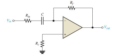
Practical Differentiator
Ideal differentiator have only a capacitor in inverting terminal. Capacitor conducts high frequency signals and combination of this capacitor and feedback resistor act as a high frequency amplifier. Electrical noise mostly have high frequency. So this combination of capacitor and feedback resistor amplify noise. This can be rectified by using a resistor in series with capacitor as shown in the figure. This resistor make the input section as a low pass filter, So output can be protected from electrical noise. A bias compensating resistor may also connected to non inverting terminal.