Colpitts oscillator is a type of LC oscillator which is designed for the generation of high frequency sinusoidal oscillations with the radio frequencies. Typically ranging from 10KHz- 300MHz. Colpitts oscillator is designed by and named after an American Engineer Edwin H Colpitts in 1918.
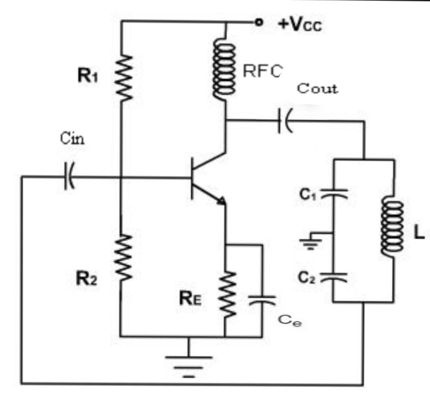
Figure shows the circuit of a colpitts oscillator. It consists of a single stage inverting amplifier and a LC phase shift network. The phase shift network consists of two series capacitors connected in parallel to an inductor, and the frequency of oscillation can be determined by the values of these capacitors and inductor of the tank circuit.
The emitter terminal of the transistor is effectively connected to the junction of two capacitors C1 and C2 which form the potential divider used for providing the feedback voltage. The voltage developed across the capacitor C2 provides the regenerative feedback required for sustained oscillations. Resistor R1 and R2 provide the usual stabilising DC bias for the transistor and the parallel combination of resistors RE and capacitor CE provides the temperature stability and bypass the amplified AC signals. A Radio Frequency Choke (RFC) is used in the collector circuit to provide a high reactance at the frequency of oscillation and a low resistance at DC to help start oscillations. The radio frequency energy developed across RFC is capacitively coupled to the tank circuit through coupling capacitor Cout, which does not permits the DC currents to go to tank circuit. The output of the phase shift network is coupled to the input of amplifier through coupling capacitor Cin. The output of the phase shift network is taken from the junction of L and C2. The capacitive feedback provides 180 degree phase shift and another phase shift of 180 degree is provided by the transistor itself. Thus a total phase shift of 360 degree is obtained which is essential condition for sustained oscillations.
Frequency of oscillation of colpitts oscillator is given by

Where,

WORKING of COLPITTS OSCILLATOR
When the power is switched ON, the capacitors C1 and C2 are start charging and after the capacitors get fully charged, the capacitors starts discharging through inductor L. During this process, the electrostatic energy stored in the capacitor gets converted in to magnetic flux which in turn is stored within the inductor in the form of electromagnetic energy. Next the inductor starts to discharge, which charges the capacitor once again. Likewise, the cycle continuous which gives raise to the oscillations in the tank circuit.
The oscillations across the capacitor C2, which have 180 degree phase shift are applied to the base emitter junction of transistor and the amplified form is appeared in the collector circuit. This output is in same phase and frequency as that of the oscillator circuit. This amplified output in the collector circuit is supplied to the tank circuit in order to meet the losses. Thus the tank circuit is getting continuously energy from the circuit to make up for the losses in it and it ensures undamped oscillations.
ADVANTAGES of COLPITTS OSCILLATOR
- Good wave purity
- Fine performance at high frequency
- Good stability at high frequency
- Wide operating range 10KHz – 300MHz
DISADVANTAGES of COLPITTS OSCILLATOR
- Because of inductor L circuit becomes bulky and cost of circuit is more
- Difficult to adjust feedback as capacitor values to be changed
- Poor isolation (bad impedance v/s frequency)
- Hard to design
APPLICATIONS of COLPITTS OSCILLATOR
- Used for generation of sinusoidal output signal with very high frequencies
- Colpitts oscillator using SAW devices can be used as the different type of sensors such as temperature sensor
- It is used for the development of mobile and radio communications
- This oscillator is prefers in situation where it is intended to withstand high and low temperature frequently.
created by : Anju Radhakrishan
Image courtesy : Google image